ThinkPad USB Port Fix
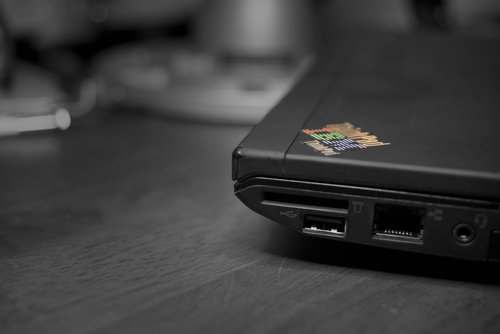
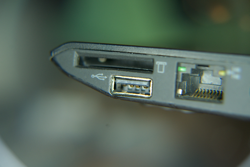
From the moment that I first had my (used) ThinkPad X220, the bottom-right USB port nearest to the SD card reader had been broken. The pad (or bolster) was missing, along with 3 out of 4 pins having been completely broken off. Needless to say this required fixing.
Damage Assessment
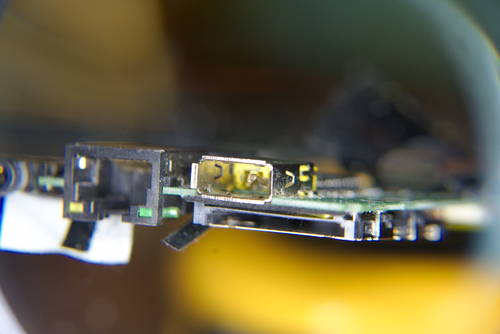
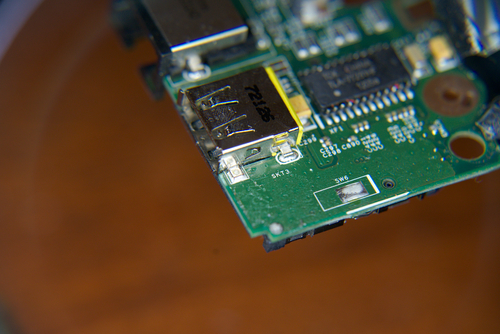
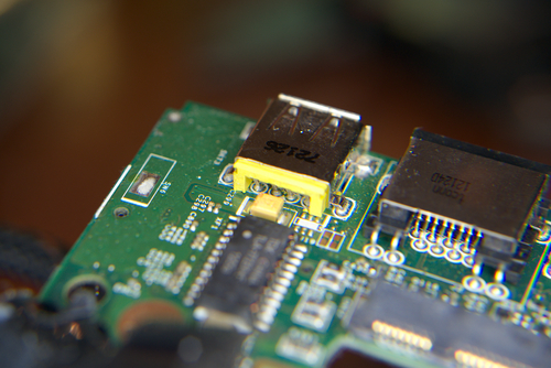
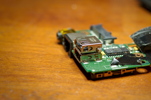
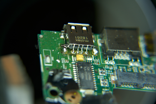
The first step was to look at the PCB to assess how this could be, if at all, replaced. From the outside you could see the damage done. Note the single pin left and lack of the inner pad (bolster?).
Measure Twice
Next on the list: measurements. To find a suitable replacement receptacle, I needed to have the relevant dimensions in comparing to receptacle part drawings of those available for sale.
Using generic, non-branded digital calipers I was able to get the following approximate dimensions:
| Description | Value |
|---|---|
| Total Length | 14.7mm |
| Total Width | 13.2mm |
| Pad Spacing (along length) | 9.1mm |
| Pad Spacing (along width) | 15.4mm |
| Pad Width | 1.9mm |
Shopping with Purpose
Using the value above, I was able to track down a USB receptacle1 on Digi-Key2 that matched my requirements very, very closely.
Resounding Comparison
Keep in mind the measured values were an eyeball approximation with a low cost, unbranded digital caliper. Those values are nearly spot-on.
| Description | Measured | Part | Difference |
|---|---|---|---|
| Total Length | 14.7mm | 14.00mm | +.7mm |
| Total Width | 13.2mm | 13.10mm | +.1mm |
| Pad Spacing (along length) | 9.1mm | 9.1mm | — |
| Pad Spacing (along width) | 15.4mm | 15.7mm | -.3mm |
| Pad Width | 1.9mm | 2.30mm | -.4mm |
The part was ordered, and arrived quickly at my doorstep. Stacked on top of each other the two receptacles matched up just as I had hoped.. Fantastic!
It’s not over yet
Initial attempts at desoldering the existing (broken) receptacle proved futile. Even with liberal application of flux, high soldering iron temperatures well beyond typical soldering temperatures3, the solder would not flow and the part would not budge. However, I was able to remove the surface mount pads though this proved useless later on.
I quickly realized it did not matter to take care in not damaging a broken part for removal. Grabbing a nearby set of flush cutters I was able to easily remove the broken receptacle! However, this wasn’t yet the end.
The leftover cutoff pins still attached to the PCB proved impossible to remove. I was able to get all through-hole header pins removed but one. After having spent about half an hour on it with tweezers, solder wick, a solder sucker (desoldering pump), and flush cutters, I gave up.
Throwing in the Towel
It turned out the only way to attach the replacement was to modify the new part to fit – luckily I had ordered two replacements as I broke the first one in the modification “process”. Cutting and bending the pins, I was able to get it soldered on (poorly). There wasn’t much wiggle room for cleaning up the bodged-in replacement; this will have to do.
The part was essentially soldered as a wholly surface mount part, which it is not. This could have future issues due to a lack of solder-terminated strain relief in connecting and disconnecting USB devices. In hindsight, I may have been able to bend the flat pads towards the entry of the receptacle down to attempt to solder them to the surface mount pads.
All the King’s horses, all the King’s men
Alas, it was time to put the laptop back together. To my dismay there were further problems. Due to the modification and forced fitment of the replacement, the USB receptacle was sticking out too far off of the PCB preventing the motherboard from correctly fitting. This was quickly solved by using a Dremel with a low-grit sanding drum and removing material off of the receptacle. The result was acceptable, and provided a tight fitment into the laptop case.
-
Typical soldering temperatures are around 315-370°C (600-700°F) ↩︎
Author Bastian de Byl
Modified 2019-02-28
License

