Make Your Ears Bern
A colleague offered a pair of Bern Bluetooth drop-in headphones to me fore free, with the catch being: I had to fix them
Don’t Turn It On, Take It Apart
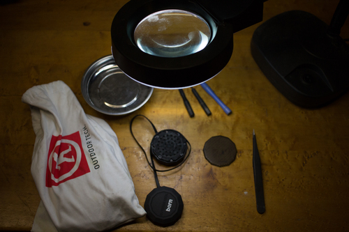
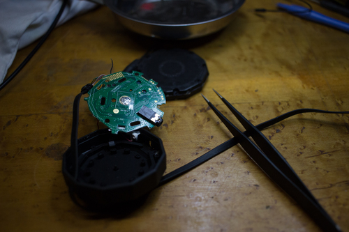
Past mistakes have taught me to be gentle and patient when it comes to taking things apart. This was no exception either. After looking over the unit on each side, I figured the only way in was lifting the mesh cover off. So I went at it, carefully, with a pair of tweezers. I worked my way around the edge and wedged the mesh upwards.
Okay, Maybe Turn It On
Now that the problematic speaker side was successfully opened without any damage, it was time to investigate what was wrong.
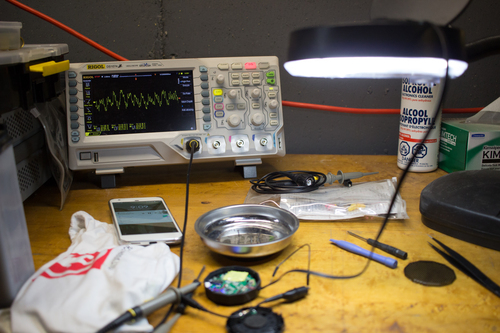
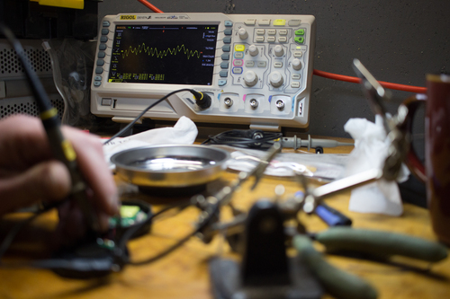
I played a song via smartphone on the speakers. The result was as expected: the right speaker put out no sound. I checked the known-good left speaker using my Rigol 1074Z oscilloscope. This may not have been entirely necessary, but I wanted to find out what to expect when troubleshooting the right channel.
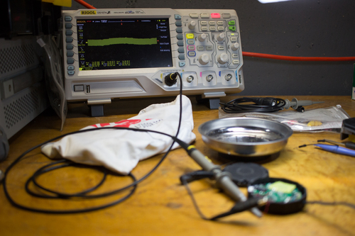
Knowing what to expect on the oscilloscope, I hooked up the probe to the right, problematic, speaker. The result was much different, indicating either noise or an open circuit. It may be worth mentioning that the right speaker was disconnected at this point in time to ease the troubleshooting process.
Where Did It All Go Wrong
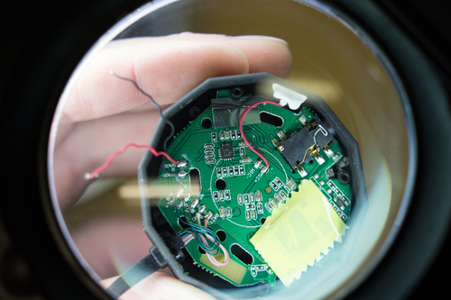
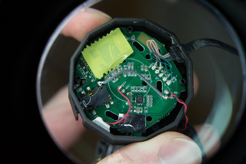
Lucky for me the PCB pads were labeled – even better SPKL+ (left) and
SPKR+ (right) were easy to find.
Outside of the bluetooth board hidden under the piece of tape, there’s not a
whole lot going on in the circuit. It was my guess that the visible surface
mount QFN chip was most likely the op-amp used for the speakers. A quick Google
search of AIWI TI (as shown in the photograph) resulted
in the following datasheet
which verified that to be the case.
Bingo! Now knowing the pinout, I could use my trusty multimeter (a Fluke
115) to test continuity of the circuit from the known-good and the now
known-bad speaker traces back to the OUTL and OUTR outputs of the amplifier.
Removing the board from the housing required a bit of finesse. I didn’t want to bother desoldering the left speaker connections to make removal easier. So, with a bit of gentle back and forth I was able to get it the PCB out and inspect traces on the bottom side.
Something’s Not Quite Right
Continuity from SPKL+ to the QFN pin was good, yet SPKR+ to the op-amp
showed open circuit. Visibly, everything on the PCB looked fine. There were no
apparent signs of damaged or lifted traces, nor bad soldered wires or
pins. Somehow the trace shortly after the chip was damaged in a way that
resulted in an open circuit at the point of the right speaker’s solder pad.
After a few minutes of scratching my head and repeatedly going over the
datasheet to check for any misunderstandings on my part, I realized the cause of
the issue didn’t matter so much. The objective was to fix the unit. I simply
needed to re-establish the connection for SPKR+ to the chip.
Using the 3.5mm mini-jack’s solder pads, I found continuity to be true from the chips left and right outputs to the conveniently accessible solder pads. A bodge wire was in order..
All’s Well That Ends Well
Again, using my trusty Fluke 115, I verified continuity from the chip’s OUTR
pin to SPKR+. Lo and behold it was now closed-circuit! I was very happy to see
the expected waveform from the known-good left channel now also appearing on the
right channel.
At this point I quickly re-soldered the wires to the speaker and enjoyed music now coming into both ears!
Author Bastian de Byl
Modified 2019-01-16
License

