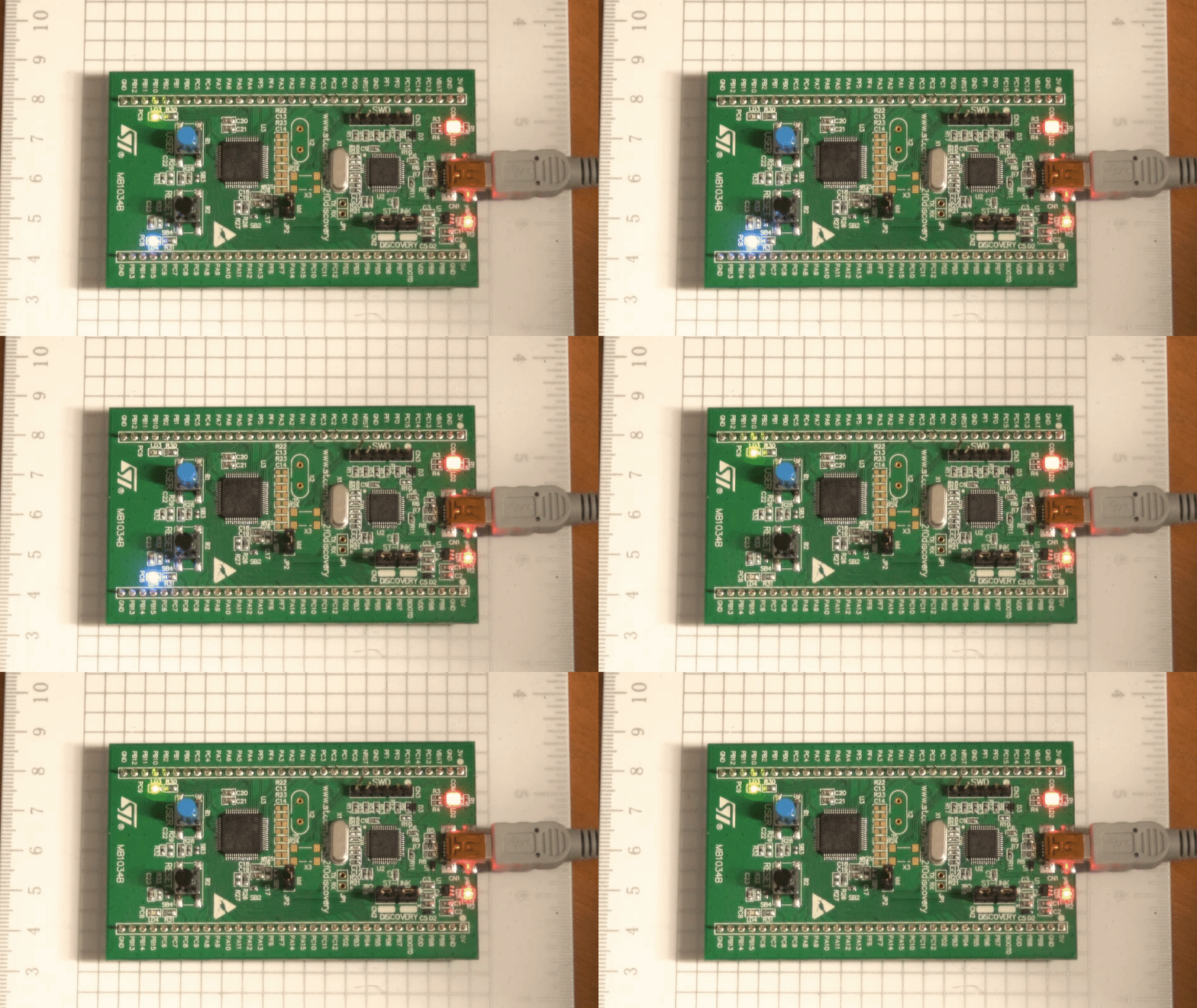
STM32F0 with libopencm3 - Part 1: Simple Timer
After having reviewed Part 0 of this series, we can now explore controlling GPIO with the hardware timers! Other tutorials have used the Systick timer as a good introduction to adding a delay for blinking an LED. However, it is my belief that this leads to confusion for beginners and only opens the door to misunderstandings. That being said, we will be using timers and their associated GPIO ports with Alternate Function modes.
Straight to the Chase
For those that want to cut to the chase and save time, here is the full source code with friendly names to get you started:
Source Code
#include <libopencm3/stm32/gpio.h>
#include <libopencm3/stm32/rcc.h>
#include <libopencm3/stm32/timer.h>

#define LED_PORT    GPIOC
#define LED_PIN_BLU GPIO8
#define LED_PIN_GRN GPIO9
#define TIM_PSC_DIV 48000
#define SECONDS     1

volatile unsigned int i;

int main(void) {
    rcc_clock_setup_in_hsi_out_48mhz();
    rcc_periph_clock_enable(RCC_GPIOC);
    rcc_periph_clock_enable(RCC_TIM3);

    gpio_mode_setup(LED_PORT, GPIO_MODE_AF, GPIO_PUPD_NONE, LED_PIN_BLU | LED_PIN_GRN);
    gpio_set_output_options(LED_PORT, GPIO_OTYPE_PP, GPIO_OSPEED_HIGH,
                            LED_PIN_BLU | LED_PIN_GRN);
    gpio_set_af(LED_PORT, GPIO_AF0, LED_PIN_BLU | LED_PIN_GRN);

    timer_set_mode(TIM3, TIM_CR1_CKD_CK_INT, TIM_CR1_CMS_EDGE, TIM_CR1_DIR_UP);

    // The math for seconds isn't quite right here
    timer_set_prescaler(TIM3, (rcc_apb1_frequency/TIM_PSC_DIV)/2*SECONDS);
    timer_disable_preload(TIM3);
    timer_continuous_mode(TIM3);
    timer_set_period(TIM3, TIM_PSC_DIV);

    timer_set_oc_mode(TIM3, TIM_OC3, TIM_OCM_PWM1);
    timer_set_oc_mode(TIM3, TIM_OC4, TIM_OCM_PWM2);

    int tim_oc_ids[2] = { TIM_OC3, TIM_OC4 };

    for (i = 0; i < (sizeof(tim_oc_ids)/sizeof(tim_oc_ids[0])); ++i) {
        timer_set_oc_value(TIM3, tim_oc_ids[i], (TIM_PSC_DIV/2));
        timer_enable_oc_output(TIM3, tim_oc_ids[i]);
    }

    timer_enable_counter(TIM3);

    while (1) {
        ;
    }

    return 0;
}
Set up the GPIO
Assuming the reader is either familiar with GPIO setup for the STM32F0, or has reviewed Part 0 of this series we will set up the GPIO pins tied to the LEDs (port C, pins 8 and 9) in the Alternate Function mode.
Knowing that we’ll be using GPIOC, we should enable this peripheral:
rcc_periph_clock_enable(RCC_GPIOC);
Alternate Functions
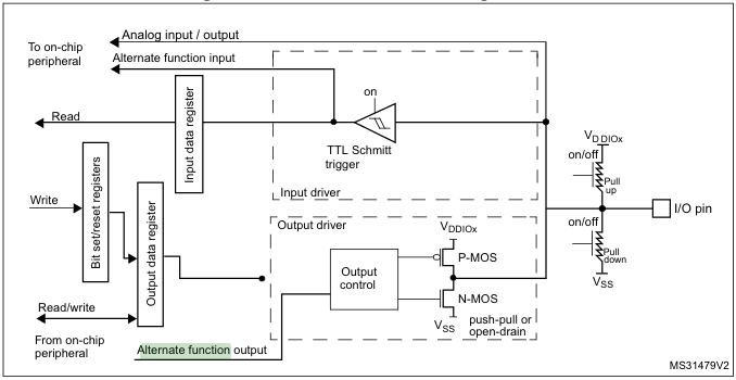
The STM32 microcontroller’s GPIO has a hardware feature allowing you to tie certain port’s pins to a different register as part of the output or input control:
For accomplishing this, a few things need to happen:
- The desired GPIO pins need to be set to
GPIO_MODE_AFingpio_mode_setup() - The alternate function mode number
GPIO_AFxhas to be set for the pins usinggpio_set_af()
Note for Different STM32Fx Microcontrollers
Review the datasheet for the specific STM32Fx microcontroller being programmed, as the Alternate Function mappings may be significantly different!GPIO Alternate Function Setup
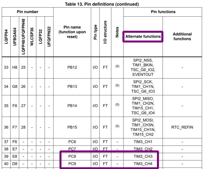
For the STM32F0 we are using in this series, the Alternate Function selection
number desired is GPIO_AF0 for use with TIM3_CH3 (timer 3, channel 3) and
TIM3_CH4 (timer 3, channel 4):
Ultimately, the code with libopencm3 becomes the following for our use case:
gpio_mode_setup(GPIOC, GPIO_MODE_AF, GPIO_PUPD_NONE, GPIO8 | GPIO9);
gpio_set_output_options(GPIOC, GPIO_OTYPE_PP, GPIO_OSPEED_HIGH, GPIO8 | GPIO9);
gpio_set_af(GPIOC, GPIO_AF0, GPIO8 | GPIO9);
Set up the General Purpose Timer
From the previous section we chose the two on-board LEDs on the STM32F0
Discovery board tied to PC8 and PC9. From the Alternate Function GPIO
mapping, we know these will be Timer 3 (channels 3, and 4).
Knowing that we’ll be using TIM3, we should enable this peripheral:
rcc_periph_clock_enable(RCC_TIM3);
Timer Mode
The first step in setting up the timer, similar to GPIO, is setting the timer mode. The encompass the divider amount (dividing the peripheral clock), alignment for capture/compare, and up or down counting:
| Divider Mode | Description |
|---|---|
TIM_CR1_CKD_INT |
No division (use peripheral clock frequency) |
TIM_CR1_CKD_INT_MUL_2 |
Twice the the timer clock frequency |
TIM_CR1_CKD_INT_MUL_4 |
Four times the timer clock frequency |
| Alignment Mode | Description |
|---|---|
TIM_CR1_CMS_EDGE |
Edge alignment, counter counts up or down depending on direction |
TIM_CR1_CMS_CENTER_1 |
Center mode 1: counter counts up and down alternatively (interrupts on counting down) |
TIM_CR1_CMS_CENTER_2 |
Center mode 2: counter counts up and down alternatively (interrupts on counting up) |
TIM_CR1_CMS_CENTER_3 |
Center mode 3: counter counts up and down alternatively (interrupts on both counting up or down) |
| Direction | Description |
|---|---|
TIM_CR1_DIR_UP |
Up-counting |
TIM_CR1_DIR_DOWN |
Down-counting |
For our purpose, it’s easier to have no division (multiplication), edge alignment, using up counting direction (can be down-counting, too):
timer_set_mode(TIM3, TIM_CR1_CKD_CK_INT, TIM_CR1_CMS_EDGE, TIM_CR1_DIR_UP);
Timer Prescaler
In addition to the timer clock, set by the peripheral clock (internal), each
timer has a perscaler value. This determines the counter clock frequency and is
equal to Frequency/(Prescaler + 1). This is the value the timer will count to prior
resetting (default behavior). We can get the exact value of this frequency,
provided we didn’t change the clock divisions via rcc_apb1_frequency (unsigned
integer value).
For the sake of simplicity in dividing the clock into easy decimal values, we will utilize setting up the High Speed Internal clock to 48MHz and dividing by 48,000:
rcc_clock_setup_in_hsi_out_48mhz(); // Place at the beginning of your int 'main(void)'
...

// SECONDS: integer value of period (seconds) of LED blink
timer_set_prescaler(TIM3, (rcc_apb1_frequency/48000)/2*SECONDS));
Timer Period
Having set the prescaler to determine the maximum count of the timer, there is an additional period we need to set. For our purposes, this will simply be the same value of the prescaler:
timer_set_period(TIM3, 48000);
Timer Additional Configuration
There are two minor settings we want to configure for the timer:
- Disable preloading the ARR1 (auto-reload register) when the timer is reset
- Run the timer in continuous mode (never stop counting, clear the status register automatically)
timer_disable_preload(TIM3);
timer_continuous_mode(TIM3);
Timer Channel Output Compare Mode
Since we are utilizing Timer 3’s channel 3 (GPIOC8), and channel 4 (GPIOC9)
we need to determine the output compare mode we want to use for each channel. By
default the mode for each channel is frozen (unaffected by the comparison of the
timer count and output compare value).
| Output Compare Mode | Description |
|---|---|
TIM_OCM_FROZEN |
(default) Frozen – output unaffected by timer count vs. output compare value |
TIM_OCM_ACTIVE |
Output active (high) when count equals output compare value |
TIM_OCM_TOGGLE |
Similar to active, toggles the output state when count equals output compare value |
TIM_OCM_FORCE_LOW |
Forces the output to low regardless of counter value |
TIM_OCM_FORCE_HIGH |
Forces the output to high regardless of counter value |
TIM_OCM_PWM1 |
Output is active (high) when counter is less than output compare value |
TIM_OCM_PWM2 |
Output is active (high) when counter is greater than output compare value |
Essentially, what we will be doing is using PWM (pulse-width modulation) at a very slow speed to create an alternating “blinky” effect on the LEDs. Using the alternating PWM output-compare modes will yield this effect:
timer_set_oc_mode(TIM3, TIM_OC3, TIM_OCM_PWM1);
timer_set_oc_mode(TIM3, TIM_OC4, TIM_OCM_PWM2);
In layman’s terms: only one LED will be on at a time, alternating.
Timer Channel Output Compare Value
Lastly, we need to set the values that the output compare looks to for it’s comparison. For this example, we want a 50%-on/50%-off time for ease of timing the duration of LEDs on-time determined by the frequency and period of the timer:
// (48,000 / 2) = 24,000
timer_set_oc_value(TIM3, TIM_OC3, 24000);
timer_set_oc_value(TIM3, TIM_OC4, 24000);
Exercise for the Reader
A fun exercise in C to reduce repetition would be by creating an array of timer output compare address values and looping through them to set them to the same value.
Garbage collection may be discussed in a future post in this series, however this is not intended to be a “How-To C” series and should instead focus on the microcontroller. That being said, there is still some fun to have.
The following snippet will be provided as a note and exercise for the reader in exploring memory allocation and garbage collection:
int tim_oc_ids[2] = { TIM_OC3, TIM_OC4 };

for (i = 0; i < (sizeof(tim_oc_ids)/sizeof(tim_oc_ids[0])); ++i) {
    timer_set_oc_value(TIM3, tim_oc_ids[i], 24000);
}
Enable the Timer
Lastly, to kick everything off we need to enable both the timer and the relevant output-compare outputs.
// Note: these cannot be OR'd together
timer_enable_oc_output(TIM3, TIM_OC3);
timer_enable_oc_output(TIM3, TIM_OC4);

timer_enable_counter(TIM3);
Another Exercise for the Reader
The same for loop for timer_set_oc_value() can be appended to
for timer_enable_oc_output() as discussed previously:
int tim_oc_ids[2] = { TIM_OC3, TIM_OC4 };

for (i = 0; i < (sizeof(tim_oc_ids)/sizeof(tim_oc_ids[0])); ++i) {
    timer_set_oc_value(TIM3, tim_oc_ids[i], 24000);
    timer_enable_oc_output(TIM3, tim_oc_ids[i]);
}
Fin
Lastly, as always, we should not forget to place the microcontroller in an infinite loop:
while (1);
The reasons for why this is done was discussed in Part 0: Turn it on!
-
The Auto-Reload Register is the value automatically loaded into the timer when it finishes counting ↩︎


